
Tetragora
Computation Research
Generative design algorithms
Chat-assisted room programs for site-constrained building layouts — from an underused plot to a selected program, then a packed envelope the robots can assemble.
Folio 15
Generative design algorithms
Chat-assisted room programs for site-constrained building layouts
We developed a design algorithm that generates adaptive architecture.
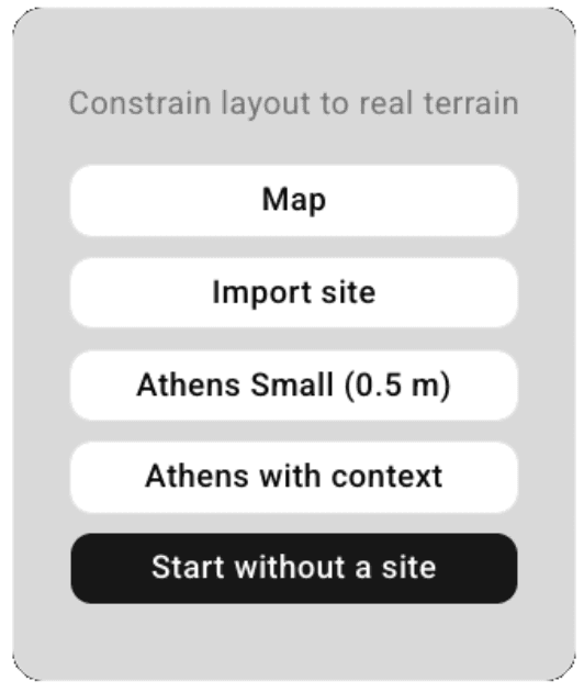
Users start by defining a building site: pick an area on the map, upload site data, or skip the plot and describe the dwelling they want — size, households, height.
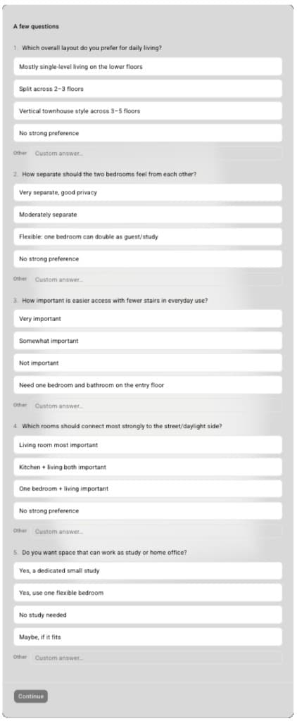
A chat assistant asks a few clarifying questions and proposes several room programs: which rooms exist, how big they should be, and how they connect.
Then they pick one variant and run layout. The app shows a 3D preview of rooms fitted into the site envelope. They can remix, edit, compose variants, and export the result as a model — or pass it to the robotic assembly algorithm to deploy on site.
Folio 17
Spatial planning, first approaches
Port-based connection logic
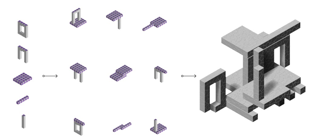
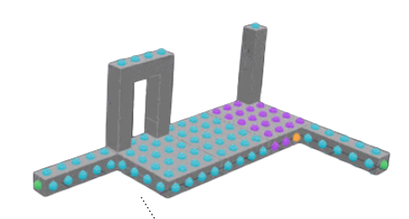
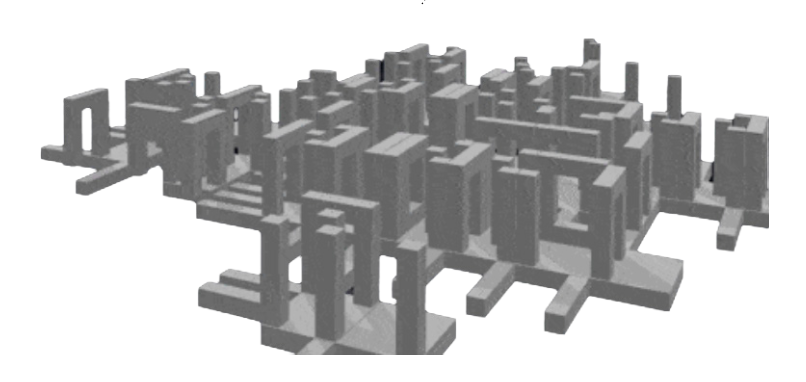
We started with procedural generation: voxel models whose connections are implicit ports on each face, collapsed by a Wave Function Collapse pass — mathematically, rather than by matching tiles by eye.
A small playground let us inspect geometries, assign connections, and export print files until the system could choose every part.
We learned a great deal about assigning and connecting voxel logic. The three-dimensional generations were not satisfying for architecture. That dead end is why the planner now writes a room program, not a tile field.
Folio 19
Tetragora platform
Spatial planning setup
Site selection and briefing happen in the same interface: a brief in steps, then a result. It is how leftover, underused land is organised with the people who will occupy it.
The layout generator talks to the user through multi-agent systems. It tries to satisfy needs and adjacencies for a given site, under the constraints of living habits and the envelope — closer to how rooms occupy a conventional building than to a one-shot massing.
They pick a site, the system offers three layouts to try, and feedback iterates the next round. The 3D preview is there so adjoining needs can change without pretending already-built space is empty.
01
Site selection
Capacity analysis
02
Design briefing
Households and rooms
03
Spatial planning
3D layout generation
04
Reconfiguration
Change of needs
Loops: reconfiguration returns to site
Site selection choices
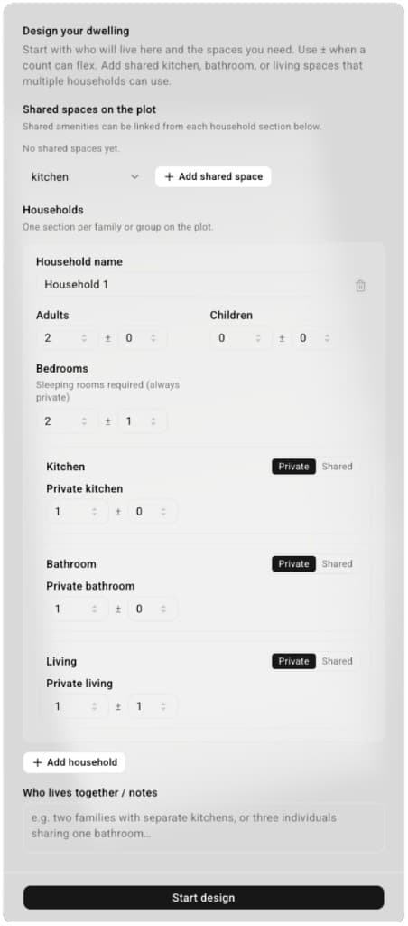
User specifies, add households
Follow-up questions
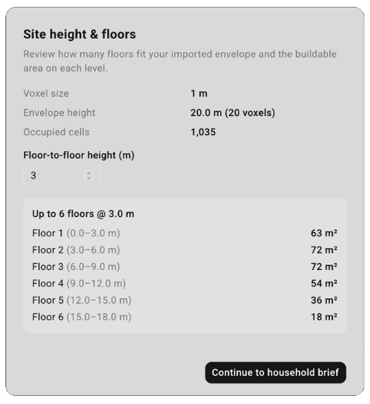
Buildable envelope per floor
Spatial planning
Folio 21
Starting the Tetragora ecosystem
Underutilised plots as a starting point
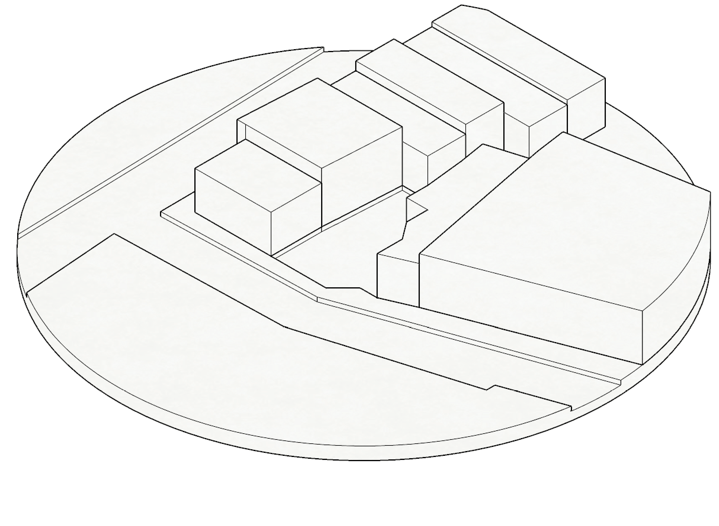
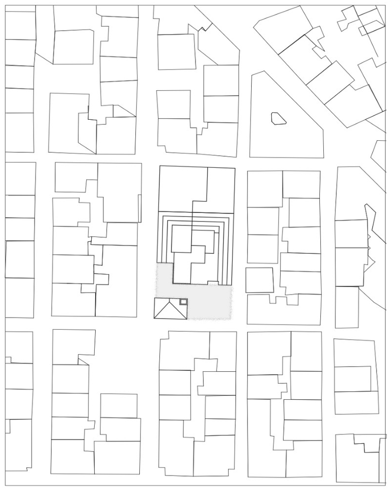
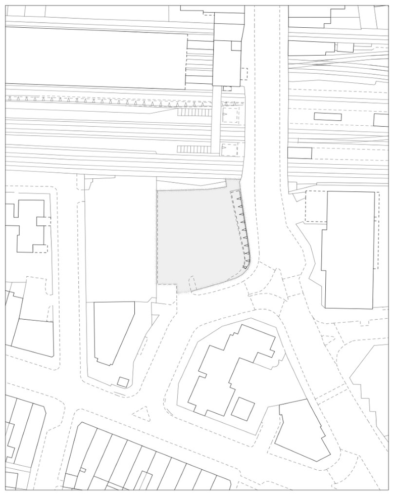
Anyone kickstarting a Tetragora project can pick a plot we already offer, search suggested sites from the map, or upload their own.
The example is from the borough of Barking and Dagenham in London — select a plot from anywhere, then voxelise it into an envelope the packer can actually fill.
Underutilised plots as a starting point
Greece
37°59'19.6"N 23°44'06.0"E
Empty plot
London
51°32'01.1"N 0°12'16.0"W
Car park
London
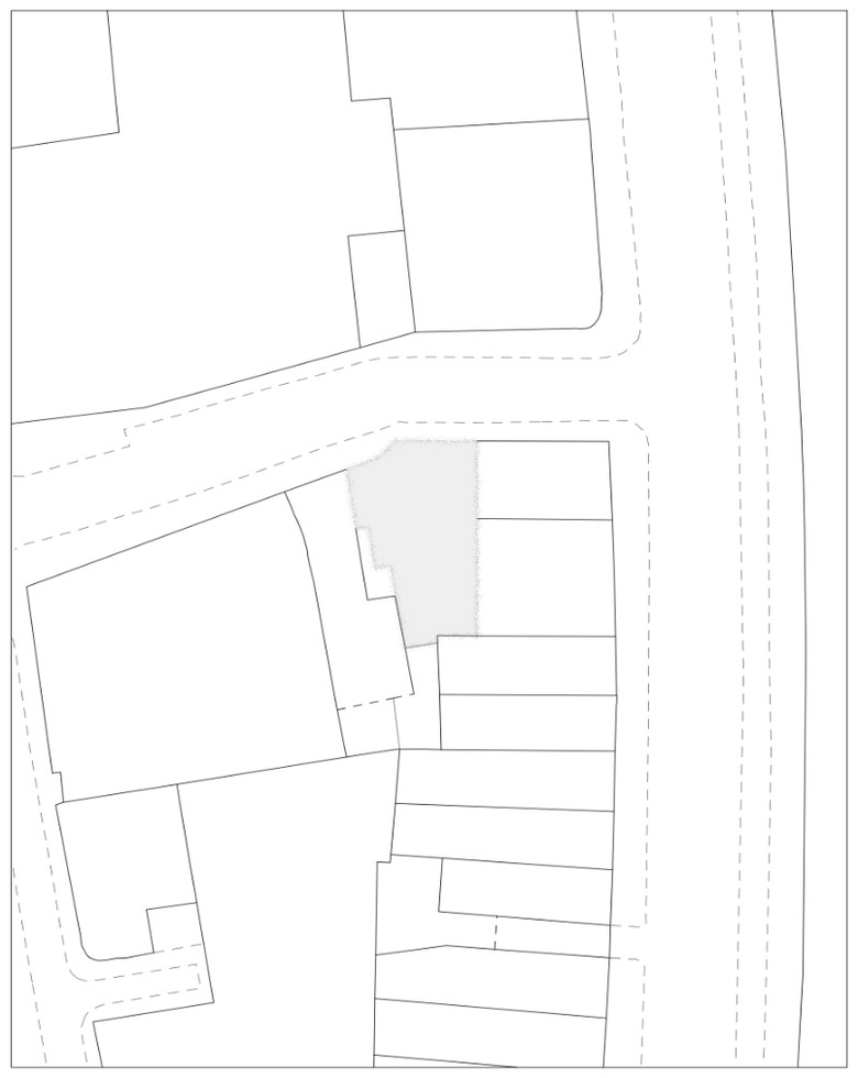
51°31'15.6"N 0°06'23.8"W
Empty plot
Denmark
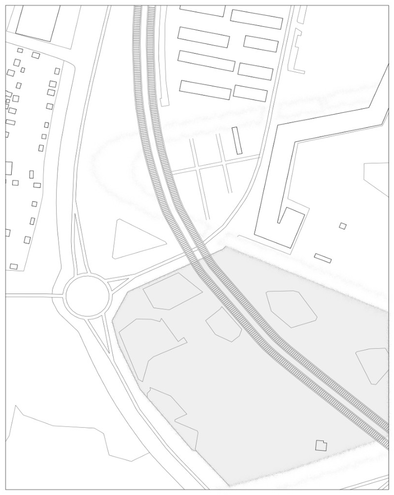
55°39'33.0"N 12°33'04.8"E
Under highway
Hastings
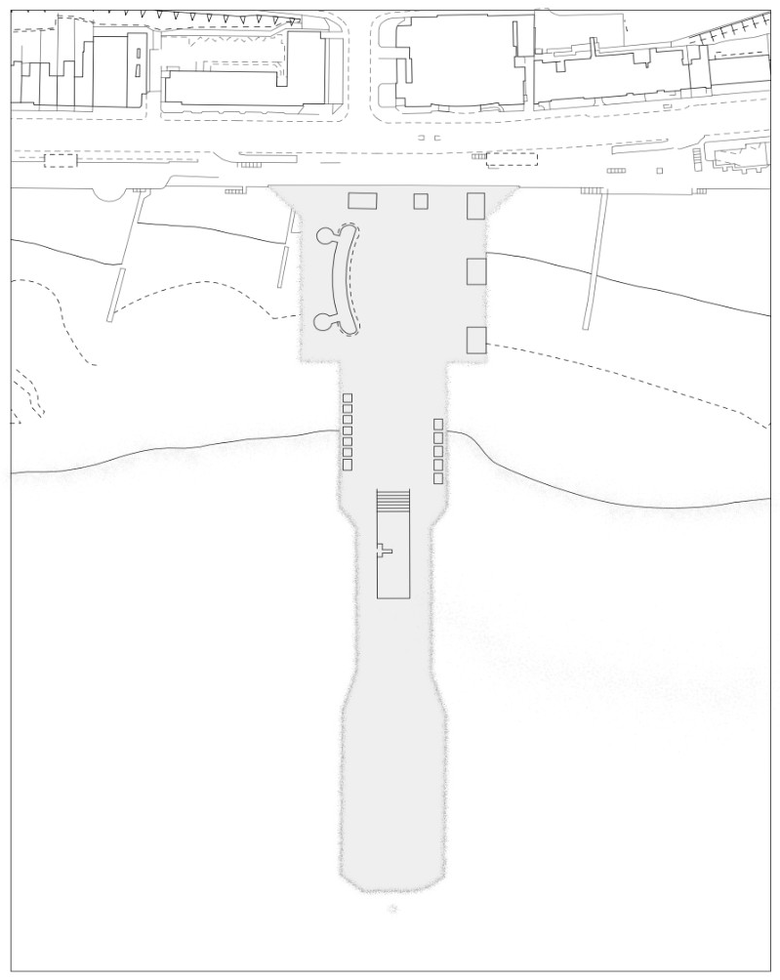
50°51'04.7"N 0°34'21.3"E
Dock
Folio 23
Voxelising the site
Then a user-specific layout generator
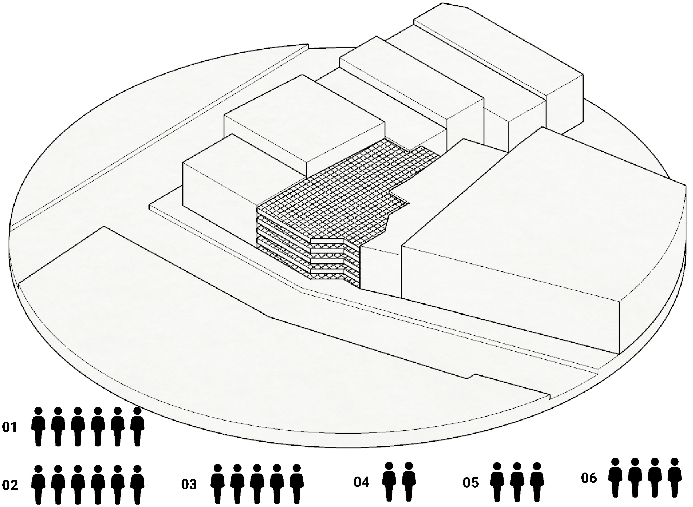
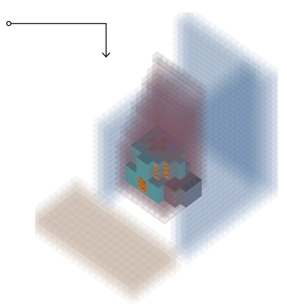
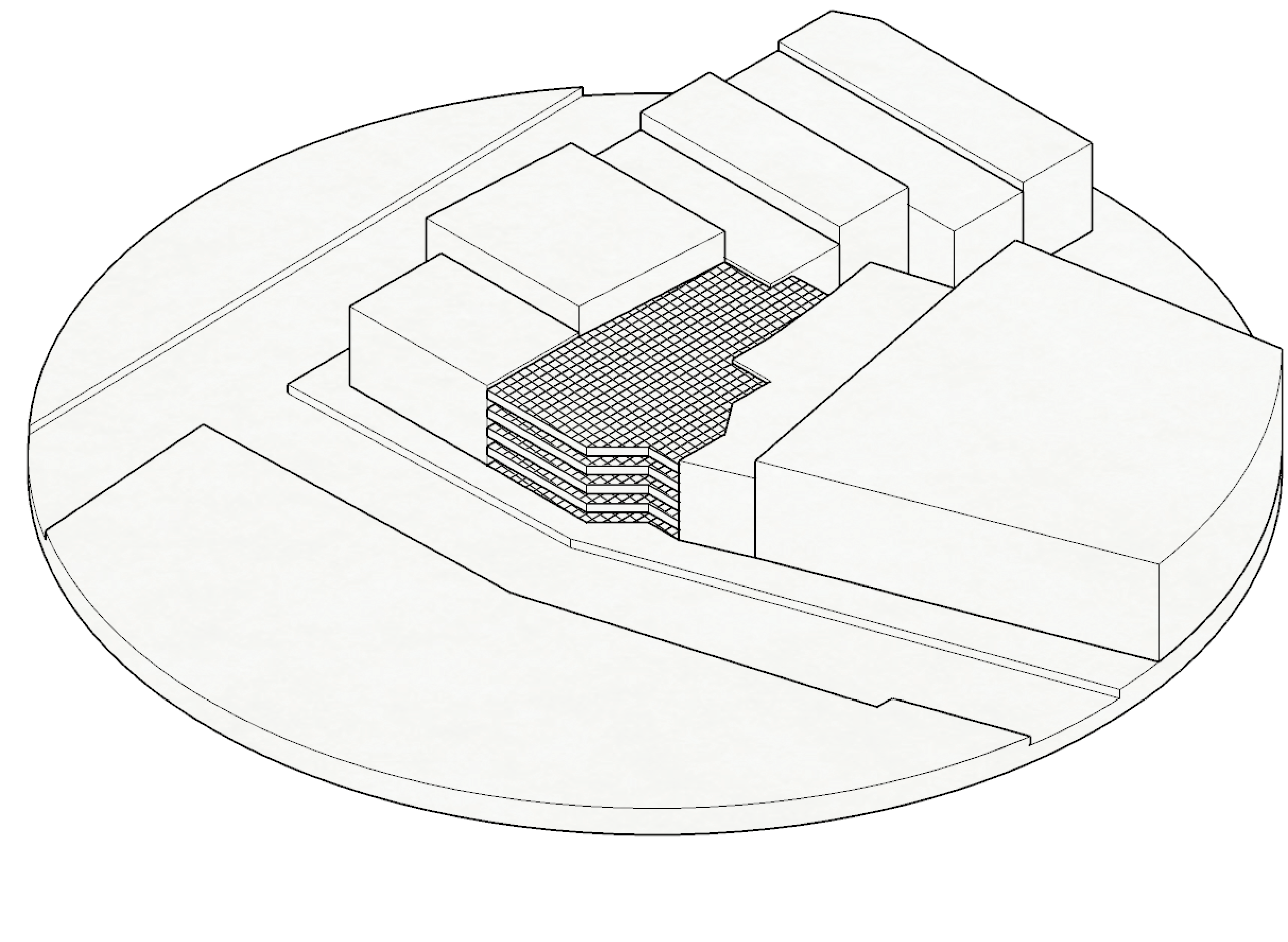
Once a site is selected, the system builds an envelope to occupy — not a rectangular slab. Each voxel is classified from open data or a scan: floor, inside, leftover. Occupancy is a slightly smaller buildable fill, not a surface shell.
Analysis slices that envelope into storeys. Floor heights sit at three metres; a floor is buildable only if its voxels run as a connected island. Columns that do not run the full height are dropped, so the program is set back from a leftover rather than forced into a uniform plate.
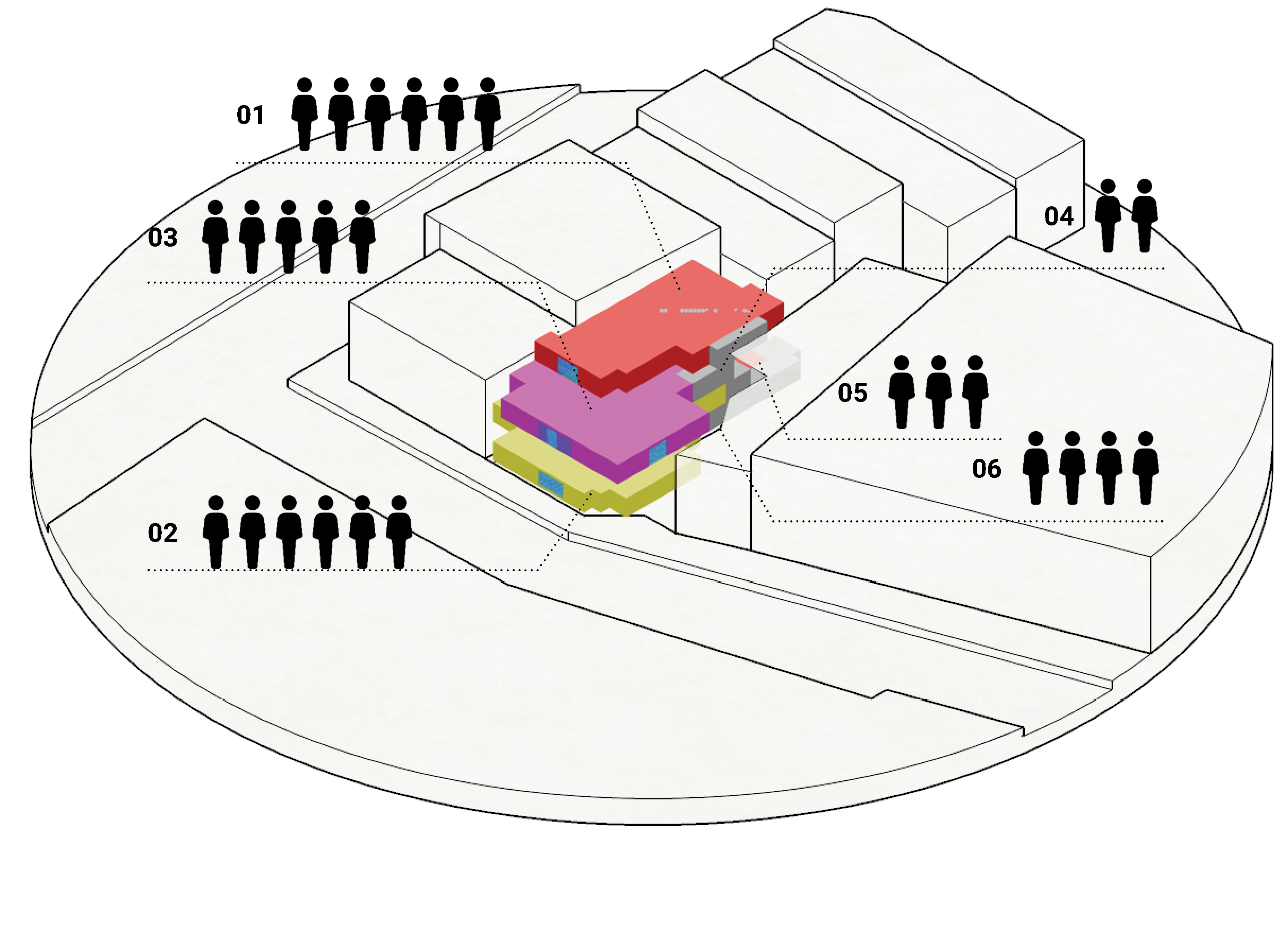
How it works
From leftover site to a spatial plan
01
Site input
Bring in a leftover plot — the gap between buildings that standard housing skips. Neighbours stay as context; the void is the site.
02
Site capacity analysis
The plot becomes a buildable envelope: height, setbacks, and a voxel grid the kit can actually fill. The hatch is capacity, not a massing sketch.
03
Design briefing
Households arrive as a brief, not a floor plan. Each cluster is a dwelling mix and a count — who lives here, before rooms are placed.
04
3D spatial planning
Rooms stack into the envelope as a coloured plan. Each household gets a place; the geometry is already a pack of modules for assembly.
The pipeline
Two spans, one run
Inputs
- User input
- Data / artefacts
- LLM agents
- BFS solver
- Viewport output
00
Inputs
A leftover plot arrives as meshes or voxels. A dwelling brief lists households, rooms, and what is shared — not a floor plan.
Site input
Voxelise (JSON)
Design parameter input
Dwelling brief (JSON)
01
Span 1 · Agent run
Main Agent delegates dwelling work. Planner Agent asks follow-ups, then emits Room Program variants — rooms, areas, and a face-adjacency tree. You stay in the loop until one program is selected.
Site capacity floor analysis
Combined design program
Main Agent
Planner Agent
Follow-up user input
questions / chat
Refinement loop
wait for feedback
Generate variants JSON
Program · Area · Adjacency
Selected Room Program
02
Span 2 · Layout generation
A BFS packer grows from the entry room and places each child on a specified face. Room boxes appear in the viewport and are scored for adjacency and envelope fit.
Layout generator
BFS face packing
Room boxes
3D viewport
Layout metrics scoring
Folio 27
LLM evaluations
Workflow, room program, and live traces
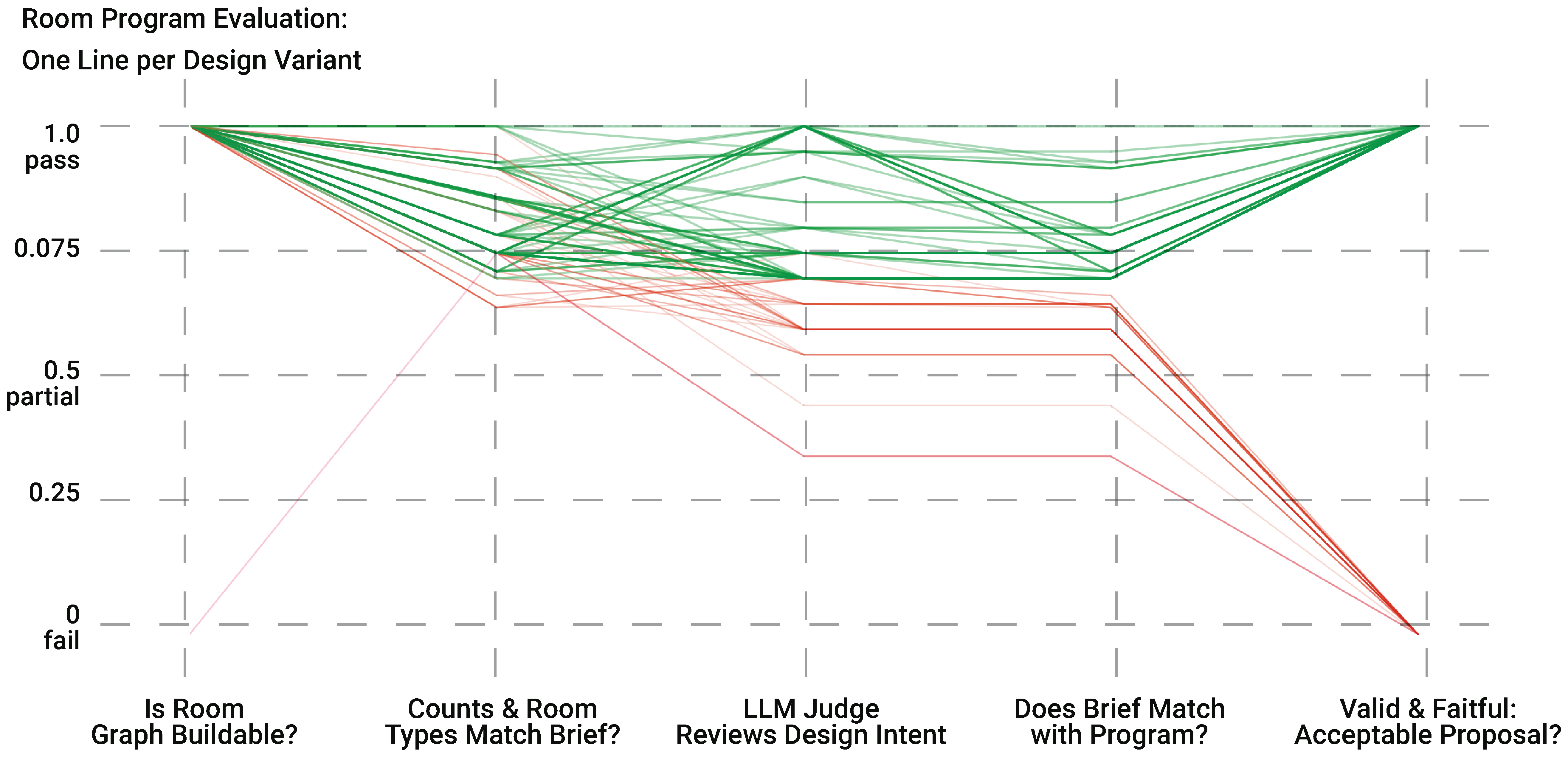
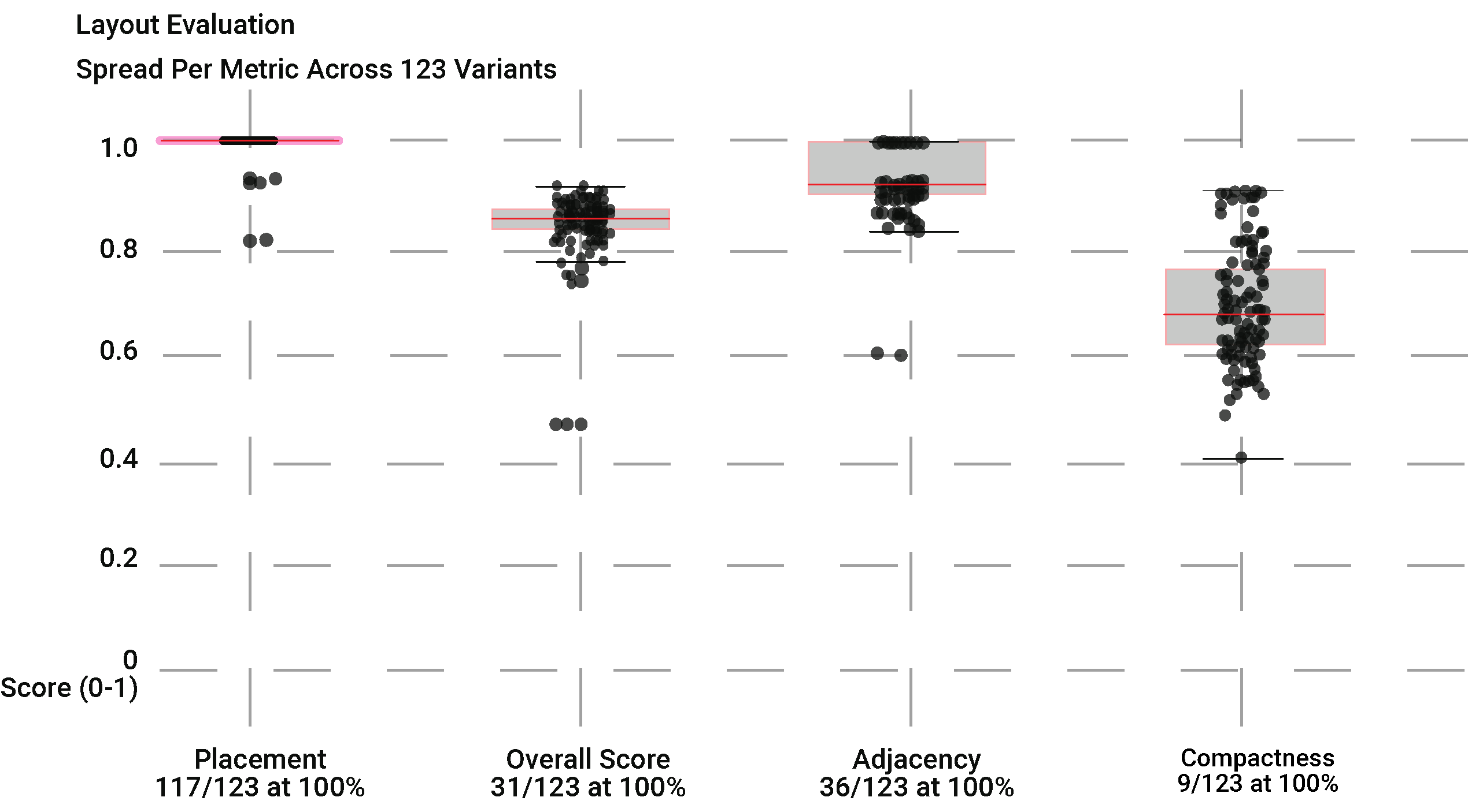
Span 1 is the agent run; Span 2 is layout generation. Between them sit three evaluation gates: a DPS check on the call itself, a program check on the JSON, and a layout check once rooms are packed.
Each design variant is a line across five questions — is the graph buildable, do counts match the brief, does the judge agree, does the brief match the program, is it valid and faithful. Green holds; red falls away.
Cost, tokens, and latency are pulled live from traces so this page stays a working instrument, not a screenshot of one experiment.
- Site + dwelling brief
- Main + planner agents
DPS evalTokenizer, latency, tokens, cost
- Room-program variants
Program evalBrief match, adjacency, graph
- User selects a variant
- Layout solver · BFS
- 3D result + metrics
Layout evalPlacement, score, compactness
cost
success
p50
runs
p95
Loading traces
Folio 33
Adjacency studies
3D layout generations
Adjacency Graph
Initial Layout

Spatial Planner
Optimized Layout

Rooms
Households

Households
Households

Folio 35
Site packing studies
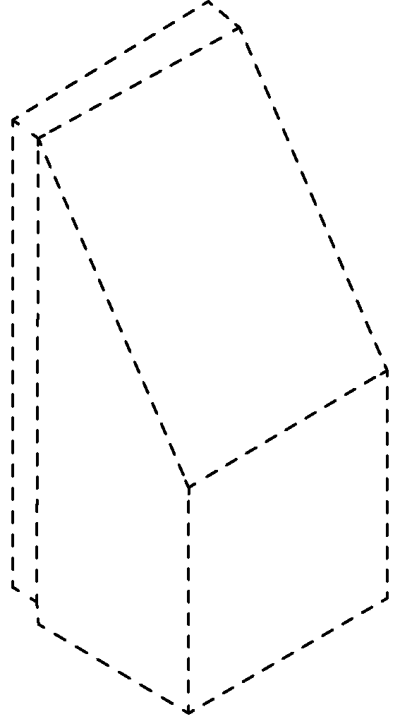
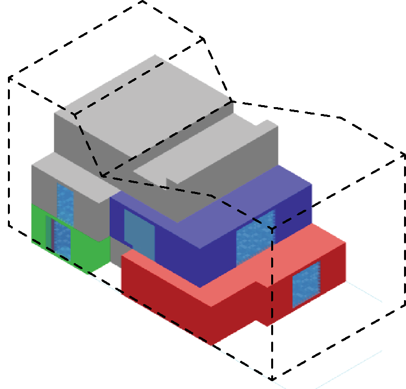
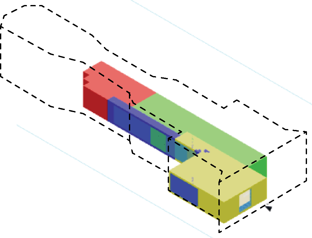
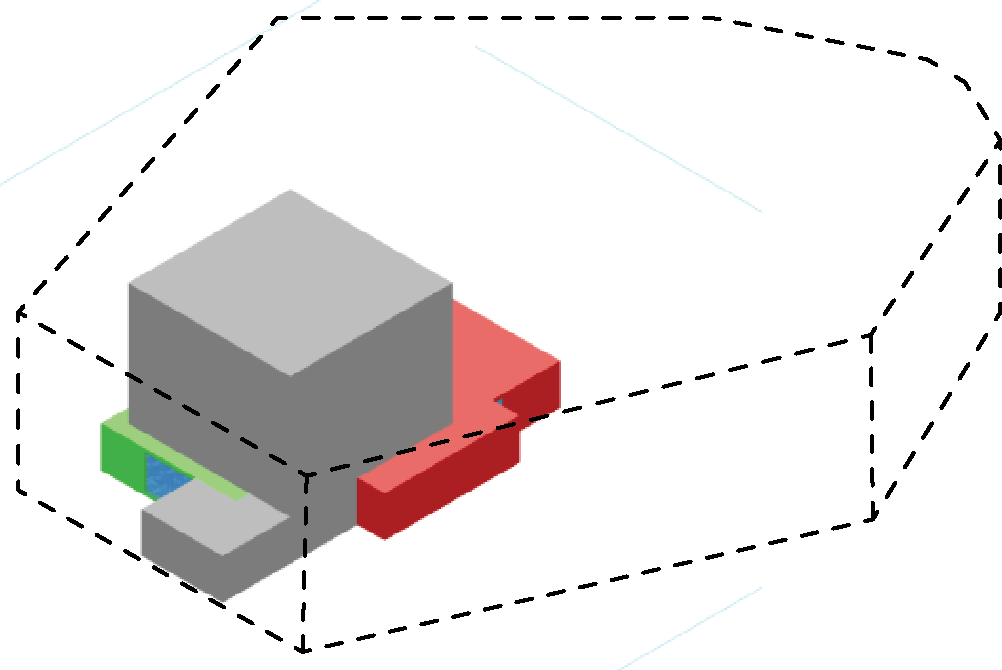
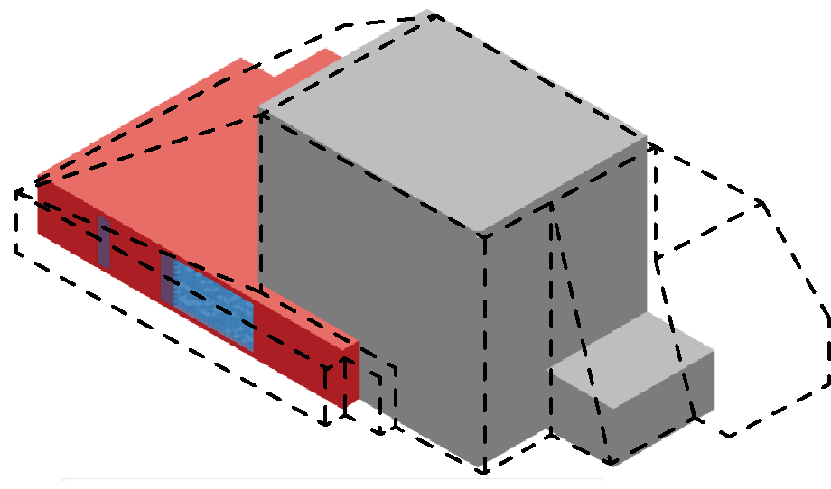
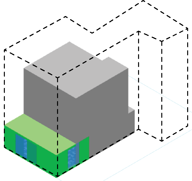
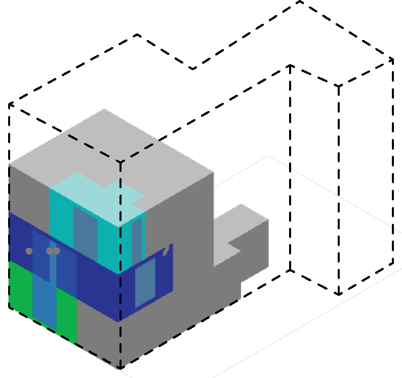
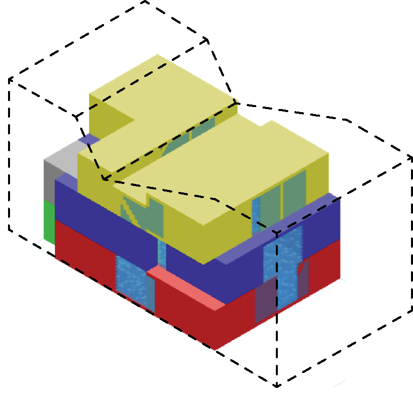
01
Site envelope model
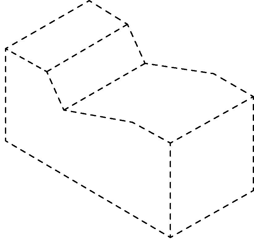
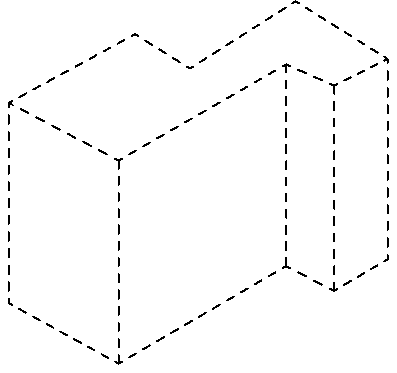
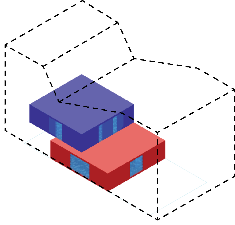
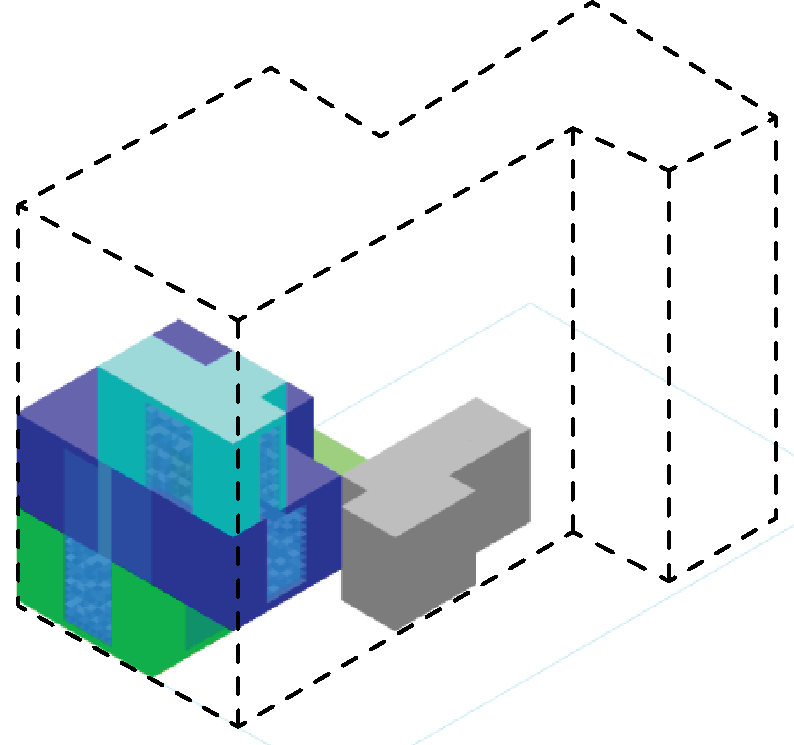
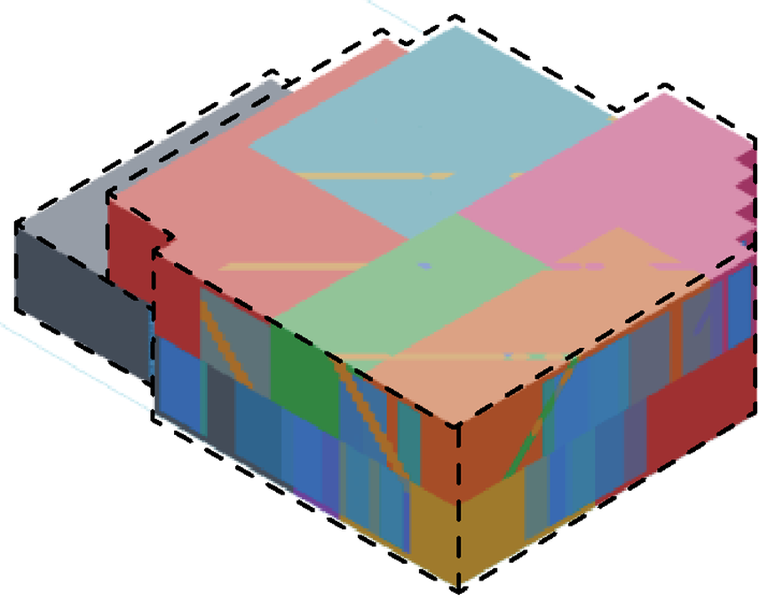
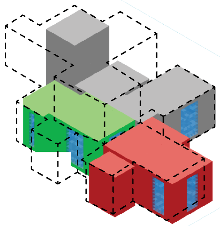
Initial layout — leftover envelopes, empty.
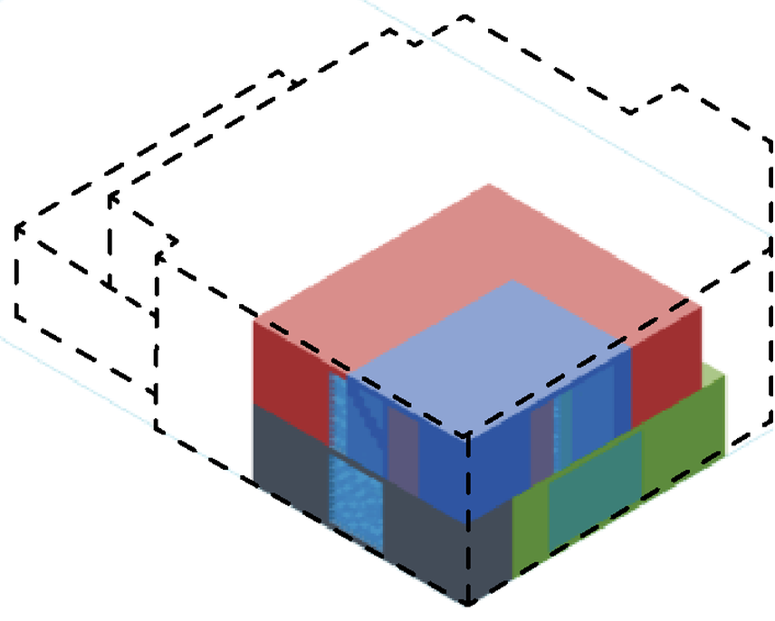
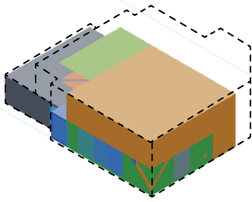
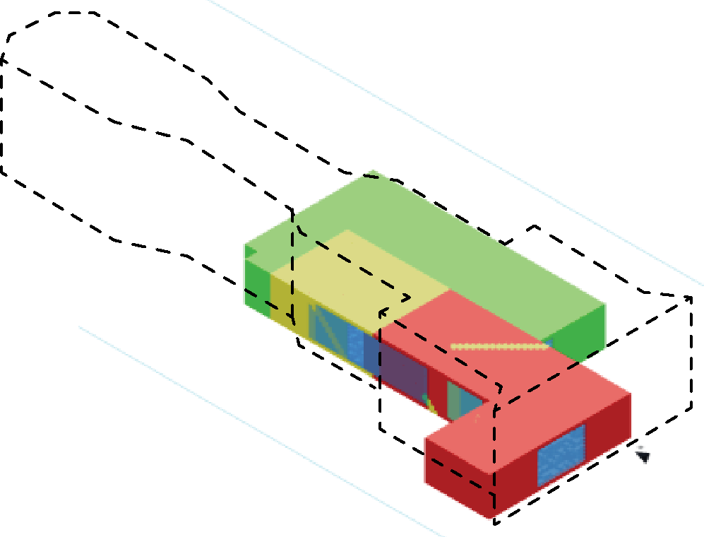
02
Fill-rate cap · 30 sec
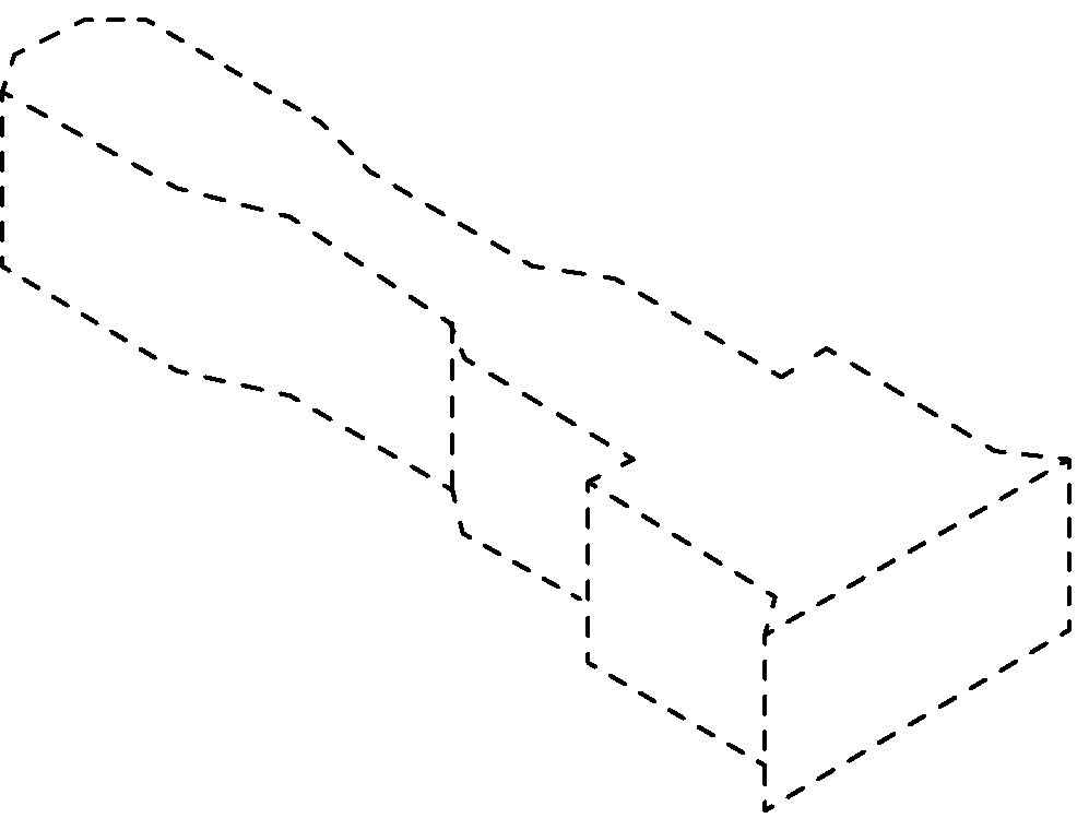
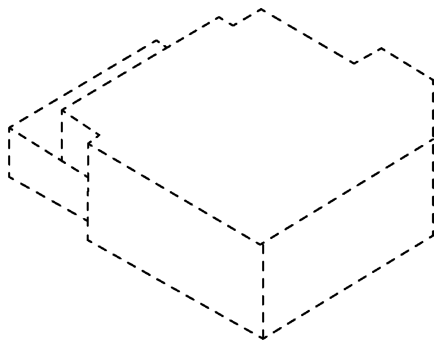
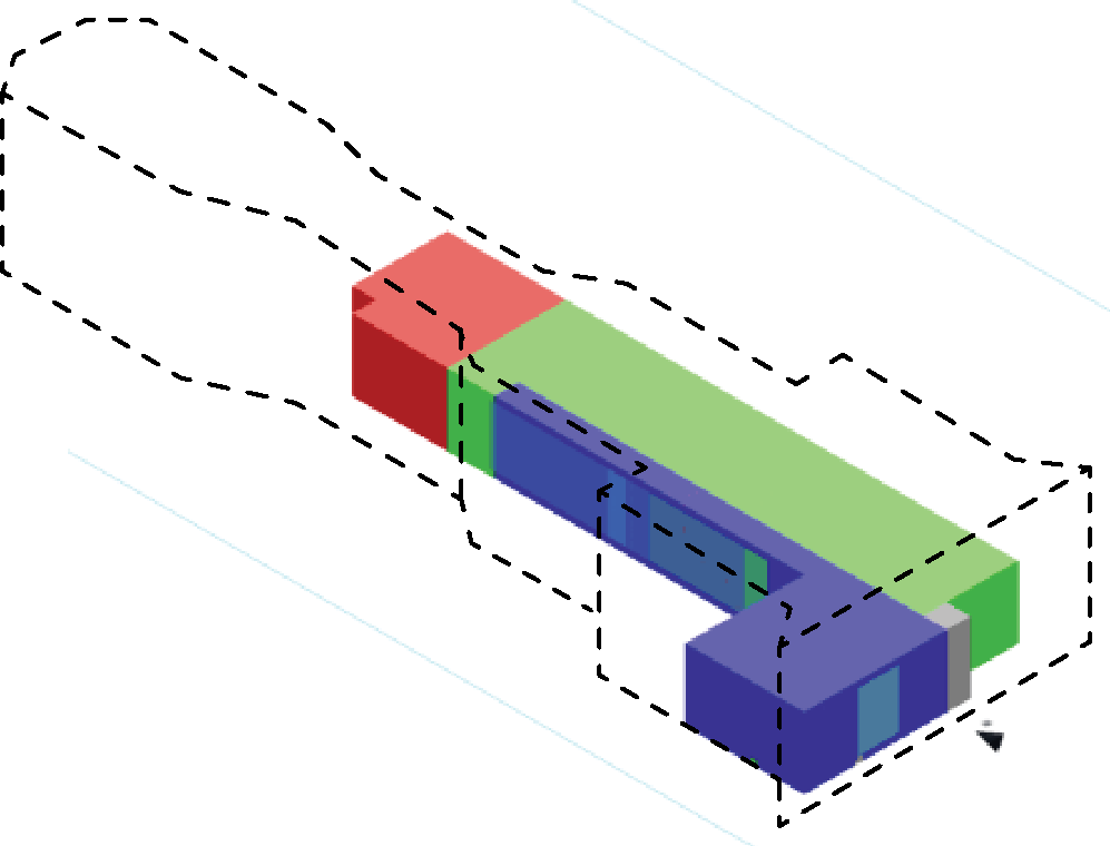
The BFS packer begins to occupy each envelope.
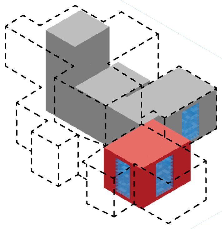
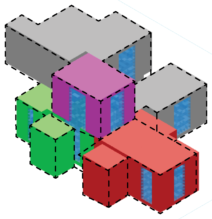
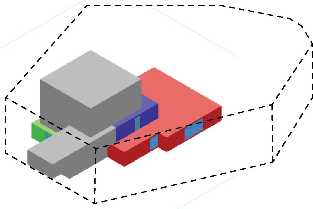
03
60 sec
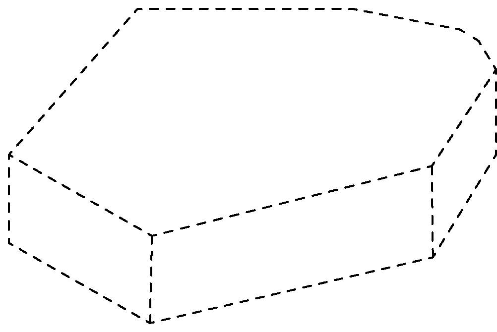
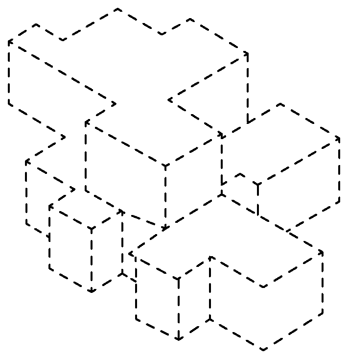
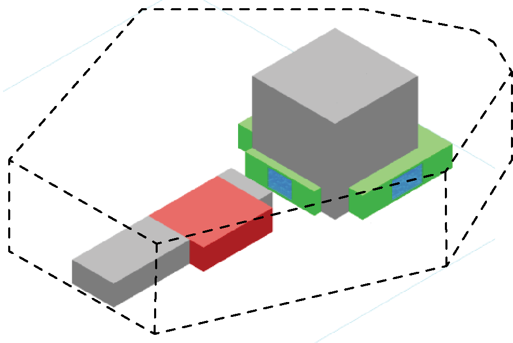
Rooms continue to grow inside the same outlines.
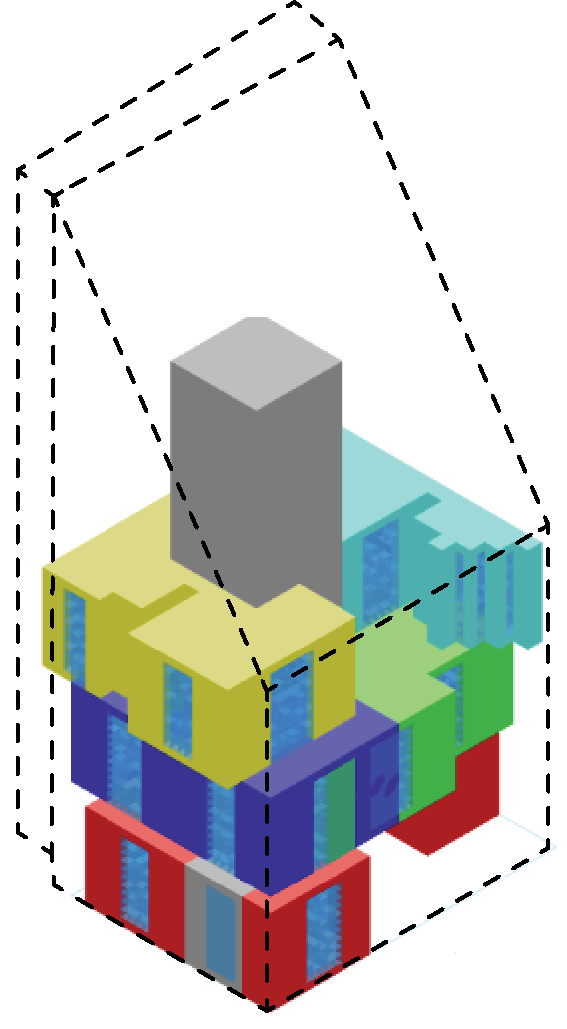
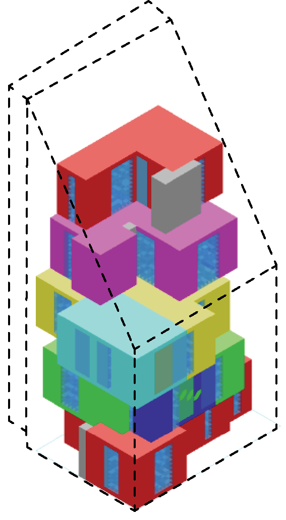
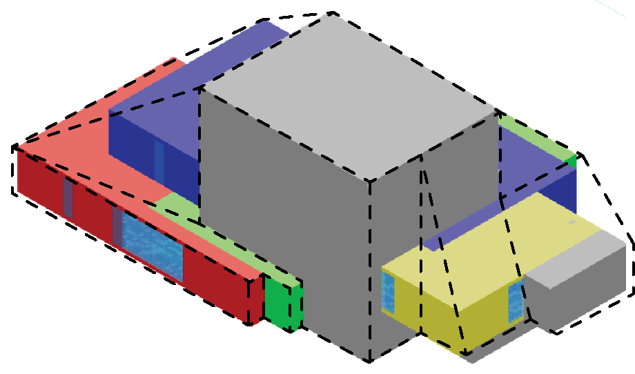
04
90 sec
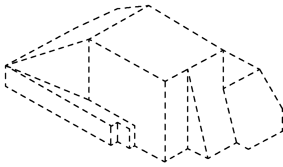
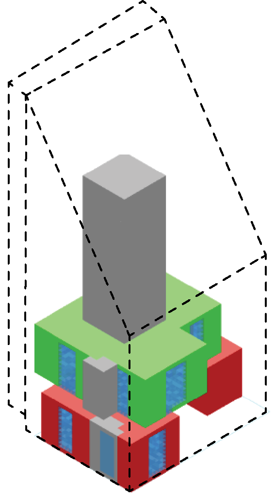
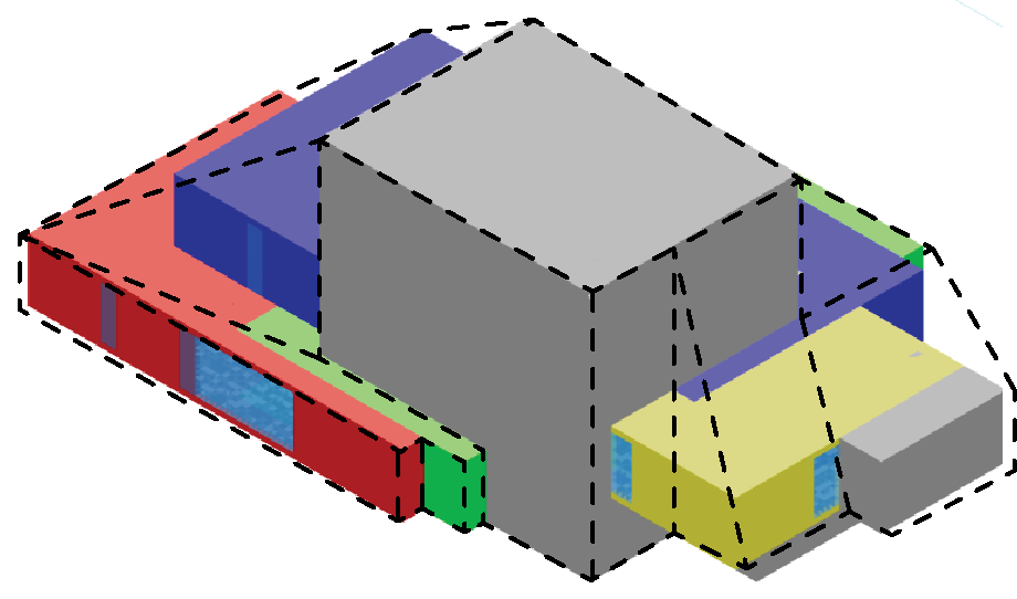
Fill-rate cap — packed leftover volumes.
Folio 79
Negotiation of users, generating adjacency graphs
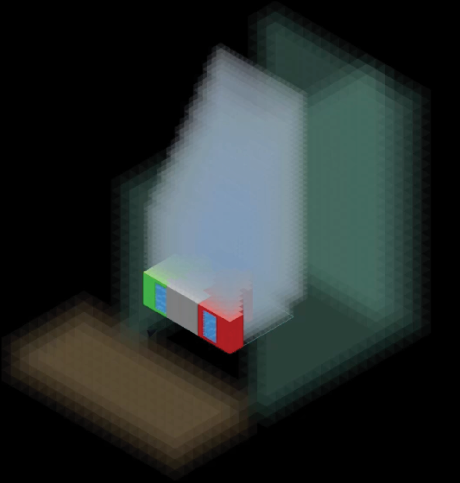
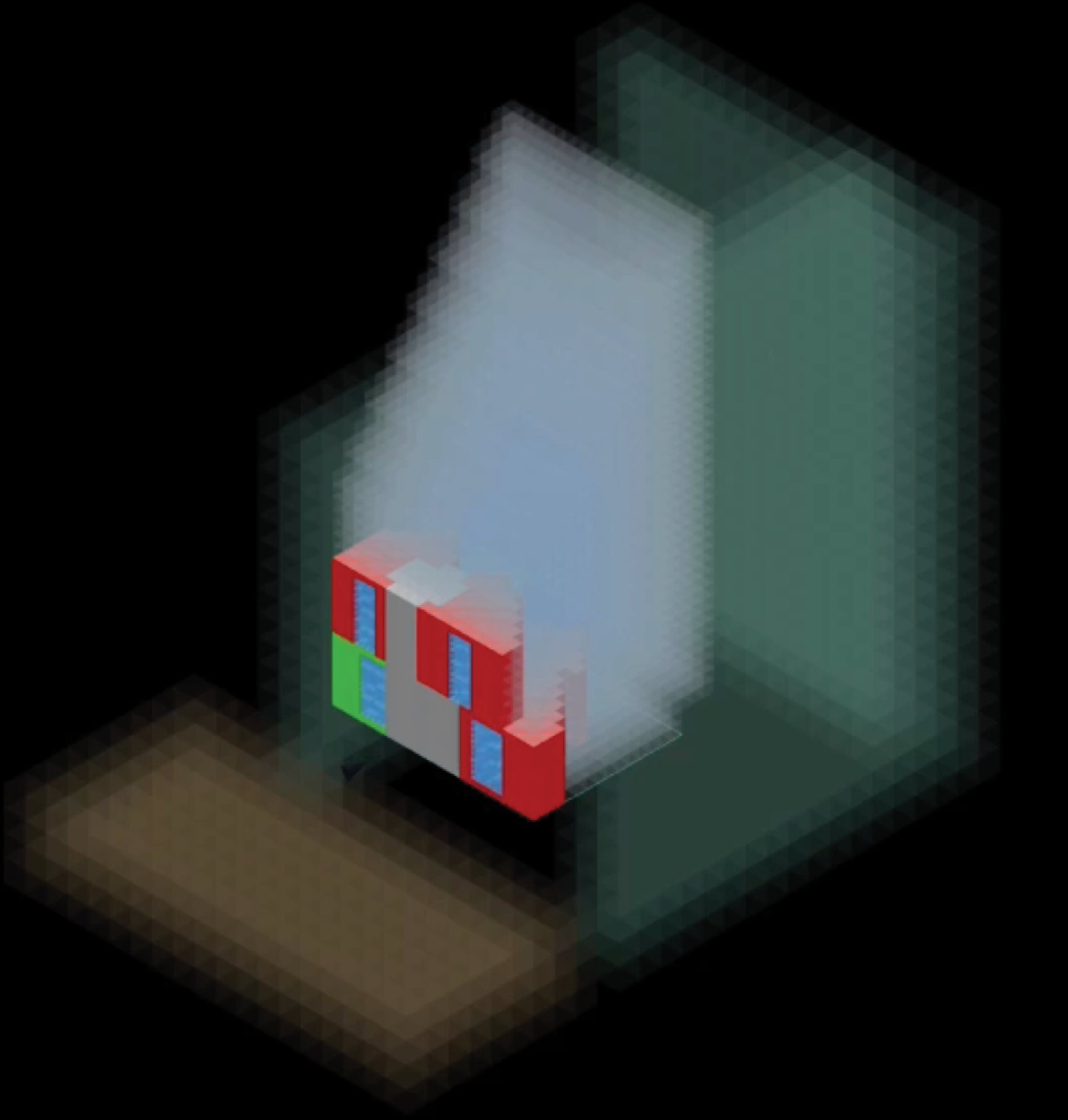
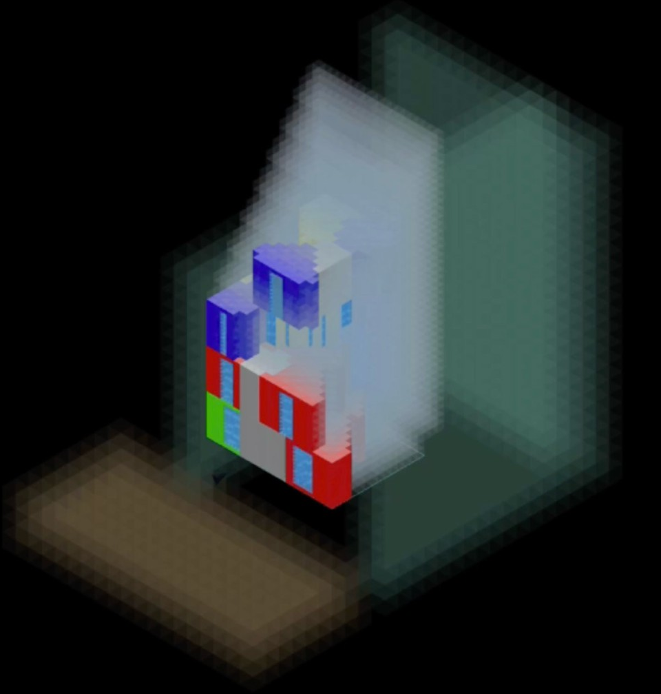
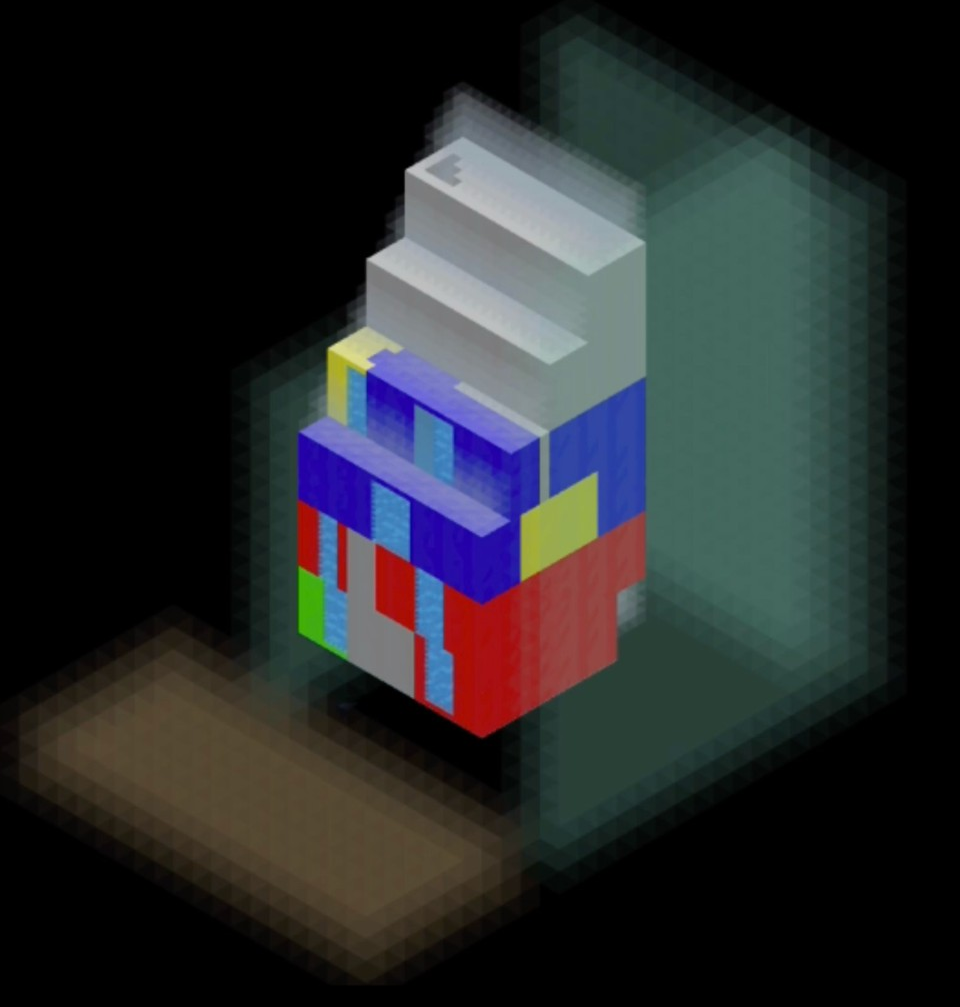
The graph exists before geometry. Rooms and directed edges are designed in the room program; the planner interviews once on occupancy, privacy, terrace, outdoor connection, then emits one to three variants.
01 Envelope
02 First rooms
03 Stack
04 Complete
Folio 81
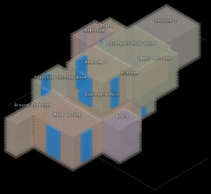
Adaptation after occupancy
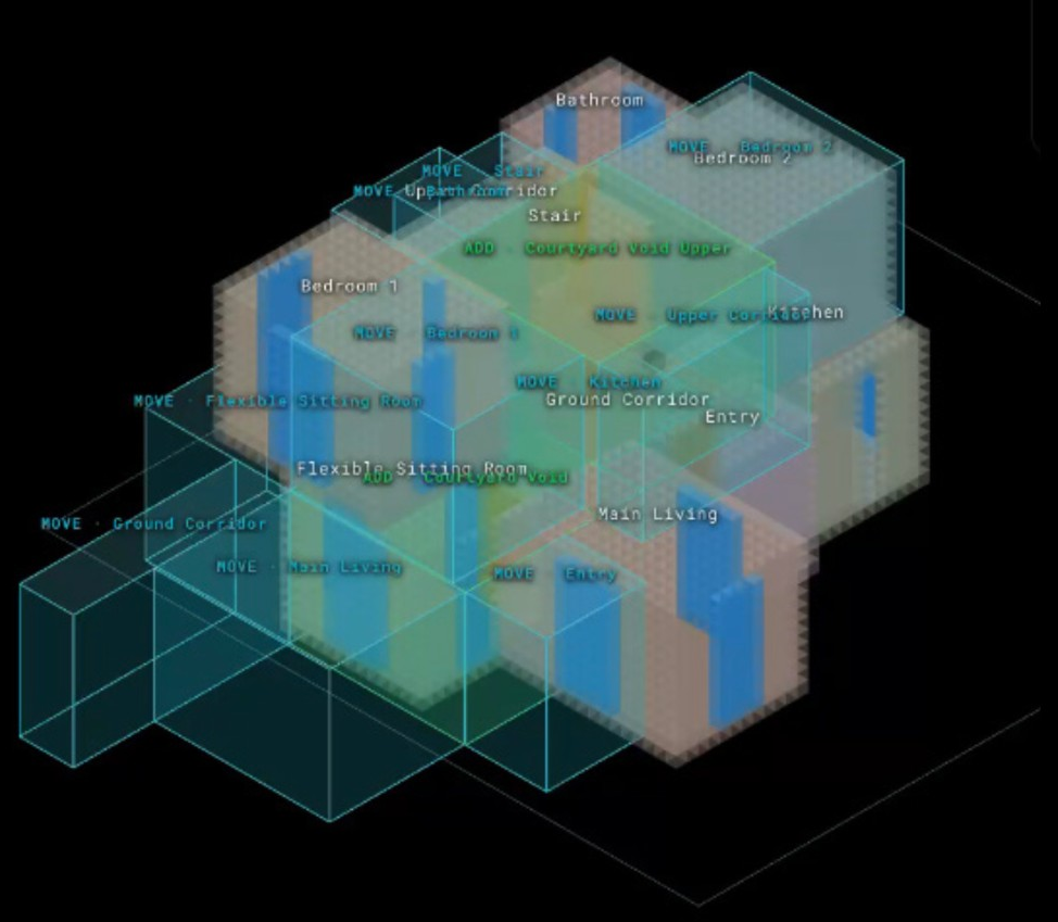
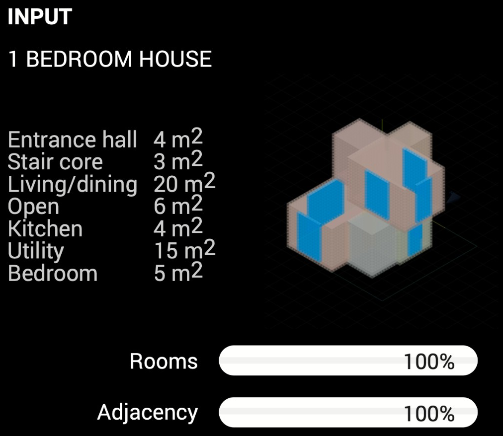
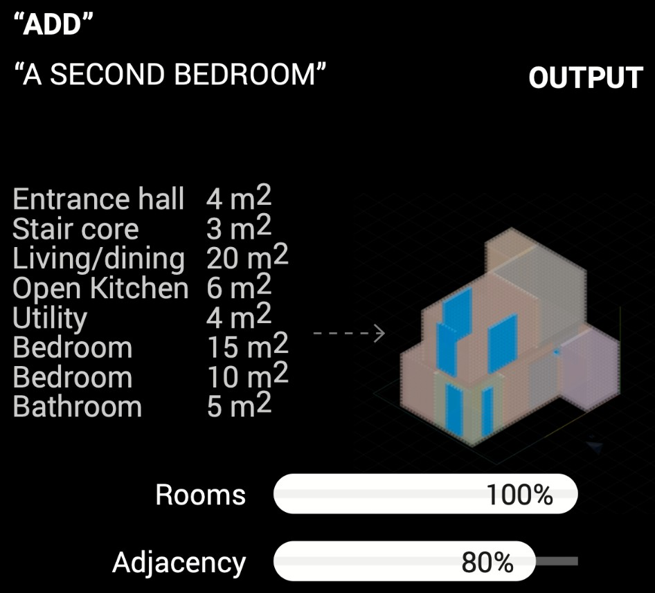
Add a second bedroom. The system previews each reconfiguration: rooms stay at 100%, adjacency drops as the graph stretches.
Open-source datasets, Swiss dwellings
Pairwise room distances from a world dataset of detailed floor plans, used to check whether LLM programs sit in a plausible range — not just a self-consistent graph.
| Bedroom | Bathroom | Corridor | Balcony | Kitchen | Living | Store | |
|---|---|---|---|---|---|---|---|
| Bedroom | — | 1.38 | 4.83 | 5.97 | 3.97 | 1.96 | 7.40 |
| Bathroom | 1.27 | — | 2.00 | 2.45 | 4.04 | 1.75 | 5.50 |
| Corridor | 1.39 | 2.50 | — | 2.83 | 2.19 | 1.84 | 4.00 |
| Balcony | 4.03 | 3.65 | 2.83 | — | 5.04 | 6.47 | 8.03 |
| Kitchen | 3.57 | 4.04 | 2.15 | 3.55 | — | 2.00 | 3.53 |
| Living | 1.93 | 1.73 | 1.84 | 2.47 | 2.01 | — | 4.54 |
| Store | 1.43 | 6.90 | 4.80 | 5.23 | 5.05 | 5.04 | — |